1.10 Systems
MP 10
The TSO'd MP 10 Voltage Converter is designed to convert 28 volts to 14 volts. The MP 10 should not be used to support two or more transceivers as should the MP 10 have a failure, both units become disabled.
Installation
The MP 10 can be mounted in any convenient place or position within the aircraft providing that it be mounted on a clean metal surface to provide good heat transfer. Secure the MP 10 to the aircraft using all four mounting holes and #8-32 hardware (screws, lock- washers, and nuts). Secure the cable with a cable clamp approximately 2 to 3 inches away from the unit.
The Installation Kit provides the necessary cable connector and nine crimp type contacts. It is best to install all nine contacts into the connector as this provides firm mating of the connector. A circuit breaker (4 amp) is also provided. It should be installed, as shown, to prevent damage to the Converter from a short circuited output.
MP 10
Weight: 1. O pound
Current Capability: 2. 0 amps continuous; 4. 0 amps intermittent duty
TSO C71 Environmental Category /BG/A/JN/AAAXXXXXX
Circuit Description
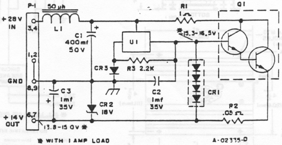
The MP 10 is a standard series pass type of voltage regulator. The input voltage may vary from 20 to 32 volts and the output voltage will remain between 13.8 and 15.0 volts with a 1 amp load.
Regulation is provided by U1, a voltage regulating integrated circuit. The output of the integrated circuit is DC coupled to Ql. Q1 is a dual transistor emitter follower which handles the high current output of the regulator.
Inductor L1 and capacitor C1 form a low pass filter which removes A+ line transients.
CR1, a multipellet diode, and resistor R2 provide short circuit protection for the regulator. If a short occurs on the output, current increases thru Q1 and resistor R2. Diode CRl will limit the voltage drop between the base of Q1 and the cathode of CRl to 2.4 volts. Thus the current out of the regulator will limit at approximately 6 amps which win then open the circuit breaker in series with the 28 volt input lead.
Diode CR3 raises the output voltage of Ul by approximately 0.5 volts.
Rl is a current limiting resistor to reduce the short circuit current under shorted output conditions.
Zener diode CR2 provides over voltage protection to the MP 10 load. If Q1 shorts, the 28 volt input would be applied to the MP 10 load. In the event this happens, Zener diode CR2 will short this voltage to ground causing the circuit breaker to open.
The MP 10 may be operated without a load, however, the output voltage will rise approximately 1 volt over its normal output voltage.

Maintenance
The MP 10 should require very little maintenance, refer to the schematic and the test voltages thereon.
Voltage Regulator, U1
Part Numbers 74020-0001 (825CU) and 74030-0001 (830) are no longer available from NARCO.
Part Number 74030-0003 (7702) is available and should be used to replace either of the above two parts, however, the SOCKET will require re-wiring. Refer to Field Service Bulletins MP-10-1 and MP-10-2 for details.
The following figures Identify the various MP 10 Chassis Levels, the voltage regulator used at that level, and how that particular component's socket was wired.
Chassis Number CNH219A. 74020-0001 (825CU). Refer to View A.
Chassis Number CNH219Al. 74030-0001 (830). Refer to View B.
Chassis Number CNH219A2. 74030-0003 (7702). Refer to View C.
Chassis Number CNH219A2. 74030-0003 (78M15HM) Refer to View C.
