2.5 Electrical Installation
2.5.1 Power And Interconnect Cable
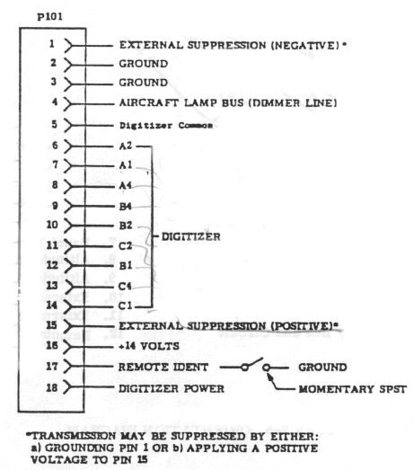
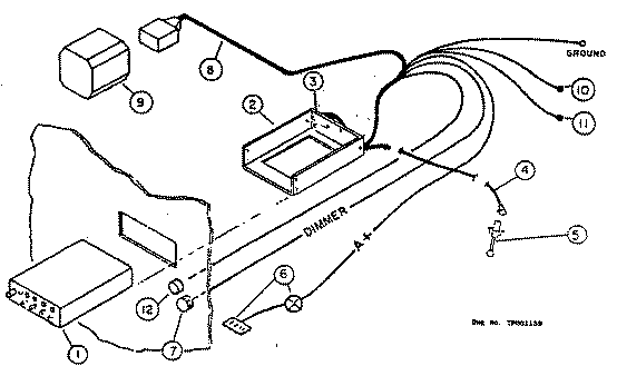
The Installation Kit provides an 18 pin Molex connector along with sufficient pins for fabrication of the power and interconnect cable. Figure 2-4 presents the electrical connections and Figure 2-5 presents a system orientation diagram.
All signal leads should be 22 AWG. A+ and ground leads should be 16 AWG. The ground lead should be connected directly to airframe ground.
A 1.5 amp circuit breaker should be provided between the unit and the aircraft power bus.

Figure 2-4 - Power and Interconnect Cable

Figure 2-5 - Orientation Diagram
| 1. | Transponder | 7. | Panel Lamp Dimmer |
| 2. | Mounting tray with Antenna Cable Assy | 8. | Altitude Digitizer Cable |
| 3. | Power Connector | 9. | Altitude Digitizer |
| 4. | Antenna Cable Extension | 10. | External Suppression (+) |
| 5. | Antenna | 11. | External Suppression (-) |
| 6. | Power Supply Bus and Circuit Breaker | 12. | Remote IDENT |
2.5.2 Cable Fabrication
- Strip wire 5/32" for PIN Terminal No. 1917-T.
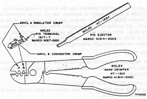
- Open tool (engraved side toward you), from the opposite side, place the conductor tab section of the pin on Anvil B. Close tool slightly (until the tabs touch the female jaw).
- Insert stripped conductor until insulation is level with outside of jaw. Crimp by squeezing handles together until jaws are fully closed or sufficient crimp is made.
- Move lead and pin to Anvil A. Crimp again until jaws are closed or sufficient crimp is made.
- If necessary, straighten pin while still being held in the jaw.

Figure 2-6 - Crimping Tool
Insertion
- The PIN terminal may now be inserted into the desired pin location in the translucent connector housing. The pin cannot be inserted upside down. Right- side-up it slides in effortlessly. Be sure to push it all the way in, until a "click" can be felt, heard, or even seen (by turning the translucent housing over).
- There is no necessity to pull back on the lead itself except to test for the "locking feature", and then only with a moderate pull.
Extraction
- If a pin is erroneously inserted into the wrong housing position, or if at some later time a circuit change is desired, the pin can be removed easily. Slip the flat narrow blade portion of the tool into the mating side of the housing, under the pin. By holding the housing upside down one can see the blade slide in, up to the stop. This action picks up the locking key and allows the lead and pin to slip out of its position using a light pulling action on the lead. Neither pin nor position has been damaged allowing re-insertion in the same or another position.
Crimping with Pliers
The lead pin Terminal connection using the Molex hand crimper provides a superior connection than with pliers. However, with care, a satisfactory connection can be made without the crimper.
- Strip wire 5/32" for PIN Terminal 1917-T.
- Using needle nose pliers, fold over conductor tabs firmly onto the conductor, one slide then the other.
- Repeat step 2 for the insulator tabs.
2.5.3 28 Vdc Operation
The AT 150 has been designed for 14V operation. Installation in aircraft with 28V electrical systems win require the addition of the external voltage converter, Model MP 10. Refer to Systems paragraph 1.10 for installation details.
2.5.4 Pilot Lamps Pilot Lamp
14/28v Switch
Commencing with AT 150 Chassis Level Code JB do not change the pilot lamp jumpers!
These units contain an external 14/28 vdc switch for this purpose. The switch, for proper lamp brilliance, should be set to agree with that of the aircraft's bus voltage.

Figure 2-7 - Pilot Lamp Conversion (Switch)
Pilot Lamp 14/28v Jumpers ( Units without external switch.)
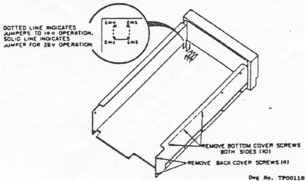
The AT 150 pilot lamps are factory wired for 14v operation. Installation in aircraft with 28v electrical systems will require that the lamp circuitry be wired in series. To connect the lamp circuit for 28v operation, refer to Figure 2-8 and proceed as follows:
- Remove the rear cover and then remove the bottom cover.
- Unsolder the jumper wire between E415 and E413 and the jumper wire between E414 and E412.
- Solder a jumper wire between E412 and E413.
- Replace the bottom cover and then replace the rear cover.

Figure 2-8 - Pilot Lamp Conversion (Jumpers)
2.5.5 External Suppression
The AT 150 transponder may be externally suppressed by other avionics equipment whose transmissions may be interfered with by simultaneous AT 150 transmissions. P101-15 may be connected to equipment that supply positive suppression pulses. P101-1 may be connected to equipment that supply negative suppression pulses.
In aircraft equipped with dual transponders, P1O1-1 of both transponders may be connected to a remote SPDT switch which will alternately suppress the transponders by placing the appropriate P101-1 at ground potential. This switch may be located at any convenient place in the cockpit and labeled appropriately.
2.5.6 Remote IDENT
P1O1-17 provides for the connection of remote IDENT switch. This switch should be a momentary SPST type and connected such that activation places P1O1-17 at ground potential. This switch may be located at any convenient place in the cockpit and labeled appropriately.
2.5.7 Altitude Digitizer
P101 pins 5 through 14 provide for the connection of an altitude digitizer. The altitude digitizer, sensing atmospheric pressure, converts pressure/altitude information into digitized altitude data. This data is then transmitted to the control center by the transponder. Narco recommends the Model AR50 for this application.