Section VIII - Top Overhaul
1. Top Overhaul
a. General
(1) By top overhaul is meant the lapping of valves and the making of necessary repairs of those parts on the crankcase which are accessible without disassembling the crankcase. It includes the removal of cylinders, pistons, piston rings and valve gear for replacement or service.
(2) The need for a top overhaul is usually indicated by not being able to get the required engine speed with full open throttle while the airplane is on the ground. It is also indicated by excessive oil consumption.
|
Note |
|
(3) Before testing the ground R.P.M. with full open throttle when determining the need of a top overhaul, the following checks must be made:
(a) Mixture control is in full rich position.
(b) Throttle level is fully open and level has full and free travel.
(c) Spark is fully advanced.
(d) All cylinders are firing properly.
(e) Tappet clearances are .008" to .012".
(f) Magneto breaker gap is .010" to .014".
(g) Spark plug gaps are .015" to .020".
(h) Magneto attaching nuts must be tight. Loose nuts may allow the magneto to move thereby altering timing. Magneto coupling bolts must be tight.
(i) Be sure that the fuel flow to the carburetor is not obstructed. Clean strainers in fuel system.
(j) Check the compression of each cylinder on the engine after it has cooled down. If the compression is satisfactory, a top overhaul is not indicated and either the ignition or fuel system is at fault.
(4) If an engine ahs been properly taken care of, a top overhaul should not be necessary before 200 to 250 hours of flying time, and in some cases, more, has elapsed.
b. Cleaning And Preliminary Operation
(1) General
(a) A top overhaul can readily be made with dismounting the engine from the plane. Only those tools in the tool kit furnished with each engine need be used for this work.
(b) Be sure the ignition switch is turned "off" so that the engine will not be started accidentally while it is being repaired.
(c) Drain the oil tank.
(2) Cleaning
(a) Remove propeller, cowling, and exhaust stacks or ring. Disconnect or remove the battery so that there will be no danger of sparks igniting inflammable substances.
(b) Place airplane in a well ventilated spot where the fire hazard will be minimum.
(c) Clean engine with suitable cleaning compound.
Caution
On account of the fire hazard, do not attempt to wash the engine before it has thoroughly cooled.
(d) Allow the cleaning compound to vaporize for the exterior of the engine.
(3) Operations Preliminary To Disassembly
(a) Place airplane in a protected dust free location which has good lighting.
(b) It will be necessary to climb around the engine installation so suitable scaffolding and padded ladders would be of great assistance.
(c) The work bench should be located in a clean place with plenty of light.
c. Disassembly of Parts From The Engine
1. General
(a) New gaskets should be installed.
Note
If new gaskets are not available, be careful in removing the old ones, and immediately place them between two wooden covers to prevent their drying and cracking.
(b) Have plenty of clean lintless cloth on hand. Never use waste ravelings to wipe parts of an engine because they tear loose and may cause damage later on.
(c) All tools should be listed and each must be accounted for upon completion of the job.
(d) As parts are removed, they should be placed upon the bench in an orderly manner and marked or tagged so that they will be returned to the proper places during reassembly.
(2) Disconnect all ignition cables from the spark plugs.
|
Note |
|
(3) Remove all spark plugs.
(4) Remove rocker arm housing covers.
(5) Remove all intake pipes by unscrewing the two nuts with which each is attached to the cylinder.
(6) Removing Cylinders
(a) On engines which use palnuts to lock the cylinder hold down nuts in place, care should be taken in removing them. Be sure that these palnuts are removed with a wrench, and are never forced off by turning the cylinder hold down nuts.
(b) The cylinders are detached by unscrewing the cylinder hold down nuts with the cylinder base nut wrench. The two rear nuts (those between the cylinder and the induction housing) are the most difficult to reach and should be removed first. The six nuts remaining may then be removed.
(c) Remove cylinders, pistons, push rods, and push rod tubes in the order of rotation, leaving the cylinder containing the master rod piston (cylinder No. 1) until last.
Caution
In performing this operation, great care must be taken that the rods or pistons do not drop against the crankcase and become marred or dented.
(d) As each cylinder is taken off, push out the piston pin immediately and remove the piston. If it is necessary to drive the piston pin out of the piston, a soft drift should be used, and the piston supported in such a manner that no dr1ving thrust is taken by the connecting rod.
(e) Never allow the piston or rod assembly to slap against the sides of the crankcase or mounting studs after the cylinder has been removed from the crankcase or while the crankshaft is being rotated.
(f) Secure seven pieces of rubber hose whose I.D. is large enough to encompass the entire section of the connecting and link rods and long enough to extend from the piston to the wrist pin. Cut these pieces along one side and install them over the connecting and link rods immediately after each cylinder has been removed.
(g) All parts so dismantled from the engine should be laid on a clean bench in the order in which they are removed.
(h) While overhauling the cylinders, cover the crankcase openings with clean pieces of cloth for protection against dust and dirt.
(7) Remove the oil screen and inspect for metal chips, dirt, etc. If metal is present, a thorough search for the source must be carried out, and steps taken to correct the trouble.
d. Inspection
(1) Inspect the crankshaft and connecting rod assemblies for abnormal wear, safe tying of retaining members, etc., through cylinder base holes in crankcase.
(2) Inspect cowling panels, fasteners, etc. for defects. Repair if necessary.
(3) Inspect propeller for nicks, burrs, fit, etc.
(4) Inspect exhaust ring or stacks for cracks, leakage at joints, condition of gaskets, etc.
(5) Remove carburetor from engine and service check in accordance with carburetor manufacturer's instructions.
(6) Completely service check the magnetos in accordance with the magneto manufacturer's instructions.
(7) Replace all spark plugs with new or reconditioned plugs. Carefully inspect the entire ignition harness for serviceable condition.
(8) Inspect all cylinder hold down studs. Remove all cylinder hold down studs that are loose, broken, or have damaged threads. Replace with the proper oversized studs.
(9) Check entire engine and ascertain that all nuts are tight in accordance with torque values set forth in the table of limits. See that all safetying is complete and tight.
(10) Inspect, tighten, and safety all engine mounting bolts.
e. Servicing the Cylinder Assemblies
(a) On all engines, it is not necessary, nor is it desirable to remove the rocker arms in order to grind the valves and they should be taken apart only when some part is damaged or indicates wear.
(b) If a rocker arm roller is stuck or shows signs of wear or excessive clearance, it should be replaced. A new roller can be fitted into a rocker arm by an authorized service station equipped with proper facilities.
(2) Grinding And Replacing Valves
(a) Determine which valves are leaking and need lapping by pouring gasoline into the valve ports. Valves which leak must be lapped or replaced.
(b) Removing Valves
1. Place the cylinder over a block of wood which should be 4-1/8 inches in diameter, 9 inches high, and rounded at its upper end to fit, approximately, the cylinder dome. It is best to have the block attached to a wooden base, so that it stands upright on the work bench. This block serves to hold the valves closed while the springs are being removed.
Note
The valve supporting tool in the engine tool kit may be used for the same purpose; but the wood block will prove the more convenient when the cylinder has been removed from the engine.
2. Remove the rocker arms and shafts in order to install the valve depressing tool. Depress the valve springs with the valve spring depressing tool. Remove the split cone, the valve washers, and the springs. Care must be taken to keep the valve washers and valve retainers separate as different units are used.
3. To avoid damaging the valve guide when removing the valve, inspect the end of the valve for burrs. If any are found, they must be removed.
(c) Reconditioning and Valve Grinding
1. After both valves have been removed, scrape off all carbon from the cylinder dome and from the valves, being careful not to mar or scratch the valve seats and the valve stems.
Note
A simple and handy fixture for holding the cylinder while grinding the valves or cutting the valve seats as described under "Complete Overhaul" , is a 6" x 12" steel plate 1/8" thick, with a 4-7/8" hole near one end of the plate. Such plates may be purchased from the Warner Aircraft Corporation. The cylinder should be attached to these plates with two 5/16" diameter bolts holding the cylinder flange to the plate. The other end of the plate should be held in a vise.
2. To grind the valves, spread a small amount of valve grinding compound around the seat of the valve, insert the valve in the guide and grind with the valve grinding tool from the engine tool kit. Repeat the operation until a good seat is obtained.
3. Wash the valves and the cylinder carefully with gasoline so that no trace of the grinding compounds remains.
4. Inspect valves with magnifying glass for cracks.
(d) Reinstalling Valves
1. Put the valves in place, being careful not to interchange those of different cylinders. The cylinder number is etched on the valve stem below the groove.
2. Put the cylinder over the wooden block tool used for disassembling.
3. Snap the circlets, where used, into their grooves from the side, and assemble the lower valve spring washer, the springs, and the upper washer to the head.
4. Depress the valve springs with the valve spring depressing tool. Insert the two halves of the split retainer, being careful that the proper type retainers and upper washer are used. Be sure that the two retainer halves used on each valve, if numbered, bear the same number.
5. After the valves have been assembled, they must be tested with gasoline for tightness, and if they still leak, the valve grinding must be repeated until they are tight.
(a) Check cylinder bores for out-of-round, taper, scores, cracks, etc.
(b) Check cooling fins for cracks, etc.
(c) Carefully check the fit of the spark plugs in the cylinders. Carbon in the threads or the effect of frequent heating and cooling may cause the plugs to become tight. If such is the case, retap with a special tap which can be procured from the Warner Aircraft Corporation.
(4) Pistons, Piston Pins, and Rings
(a) Cleaning and Servicing Pistons
1. Remove all the rings from the piston by spreading the ends apart until each ring can be pulled out of its groove over the top of the piston.
2. Scrape the carbon from the top surface of the piston and then polish by rubbing it on a piece of kerosene soaked crocus cloth, spread on a flat plate.
3. Remove all carbon from the ring grooves.
4. Inspect the piston for cracks and scores.
5. If there are any sharp edges or scratches on the pistons or in the cylinder wall surfaces, they should be carefully removed by stoning with a fine grade oil stone which has been dipped in kerosene.
6. When a defective piston is replaced, the new piston must be selected so that its weight does not differ more than 1/4 ounce from the others. When ordering pistons for replacement, please state the engine number. Records are kept of the weights of the pistons originally furnished in the engine. Therefore, pistons of the proper weight can be shipped when the engine serial number is furnished.
(b) Servicing Rings
1. Remove all carbon from rings and make sure that they are not damaged.
2. If the engine is equipped with expander type oil rings, it is highly recommended that new expanders be installed at the top overhaul in all cases; rings and shims showing no scratches or other signs of wear may be reinstalled. The use of new expanders greatly facilitates the reseating of the ring. Best results may be derived from the top overhaul if a new complete expander type ring assembly is installed.
3. Test tension of rings. Refer to the table of limits.
(c) Piston Pins
1. If plugs are loose install new ones.
2. Magnaflux pin to check for cracks and possible failure.
3. Check for fit in piston and connecting rod bushing.
(a) Be sure that all parts are absolutely clean and in good condition.
(b) The ring gaps must be staggered so they do not line up causing blow-by with excessive oil consumption.
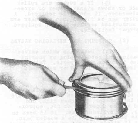
Figure 4. Checking Piston Ring Side Clearance in Piston.
(6) Assembling Rings To Four Ring Pistons
(a) The rings furnished by the Warner Aircraft Corporation are fitted and inspected in regard to the proper gap width. See Table of Limits for this width.
(b) The fourth (bottom or oil control) ring must be placed on the piston in such a manner that on pistons No. 1, No. 2, No. 3, and No. 4, the ring gap is on the exhaust side of the cylinder. In other words, when looking at the top of the piston with the number on the piston toward the observer, the ring gap should be to the right and at right angles to the piston pin. On pistons No. 5, No. 6, and No. 7 the arrange is reversed. The ring gap should be on the intake side (to the left when looking at the top of the piston when facing the numbering).
(c) The rings must have the side clearance and gap specified in the Table of Limits (see Figures 4 and 5).
(d) All rings must be installed to obtain approximately 90 degree spacing between the four gaps of the rings on each piston.
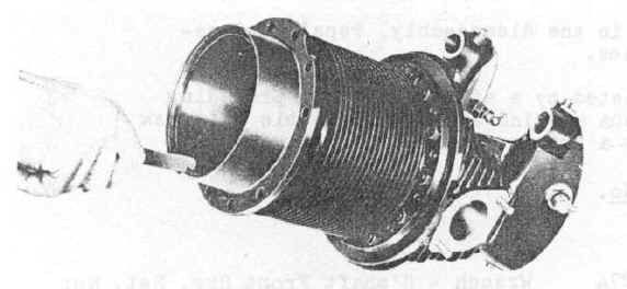
Fig.5 Checking Piston Ring Gap (Closed) in Cylinder Barrel
(7) Assembling of Pistons to Cylinders
(a) It will be found advisable, if new rings are assembled to the piston, that because of the tight fit of the rings, the piston be put in the cylinder while it is on the bench.
(b) Oil the piston generously.
(c) Use a piston ring clamp to hold the rings in place. Great care must be taken when putting the piston ring clamp on the piston that the rings actually slide into the grooves while the clamp is slowly tightened. To help the rings slide into the grooves, the clamps should be lightly tapped with a block of wood or the end of a screwdriver.
(d) Holding the numbered end toward the propeller end, the piston should be pushed in to such a depth that all the rings are in the cylinder, but not so deep as to cover the piston pin hole. The piston pin can then be pushed in while assembling the unit to the engine.
(8) Assembling of Cylinders and Pistons To Engine
(a) Install new cylinder base "0" ring packings on cylinder skirts or new cylinder base gaskets on the cylinder mounting pad on older type engines.
(b) Turn the crankshaft to a position in which the connecting rod of No. 1 cylinder extends the maximum distance outside the cylinder flange and the cam followers are in the lowest position.
(c) Holding the cylinder assembly, line-up the piston pin hole in the piston with the bushing in the rod and with the number on the edge of the piston facing the propeller. Insert the piston pin.
(d) Push the cylinder on to the piston so that it is even with the bottom of the piston skirt. When installing cylinder, squeeze the fourth ring, if provided, with the fingers.
(e) Slip a steel washer between the new packing and the shoulder on the inner end of the push rod tube.
(f) On the outer (longer) end, assemble the spring, the washer, and the packing, in the order given. In the event the spring may have taken a set, two packings may be installed to increase the spring tension. This is only possible on the push rod tubes which do not contact the packed cam follower guides.
(g) Dip both ball end of each push rod into the rocker arm grease then place the push rods into the tubes with marked end toward the rocker arms. The rods are marked alphabetically, starting with "A" for the exhaust side of the cylinder No. 1 and follow around the engine clockwise order, as viewed from the rear.
(h) Holding a push rod tube assembly in each hand, push the cylinder into place on the crankcase with the body, at the same time guiding the push rod tubes into place.
Note
The long end of the push rod tube with the spring, washer, and packing is inserted into the head of the cylinder.
(i) Install and tighten cylinder hold-down nuts using cylinder base nut wrench. Tighten nuts with desired torque as outlined in the Table of Limits.
Caution
Do not exceed torque limits.
(j) When palnuts are used, they should be tightened only 1/4 turn after coming in contact with the cylinder hold-down nuts.
(k) After cylinder No. 1 has been assembled to the crankcase, all other cylinders should be assembled in numerical order in the same way.
(l) On the intake pipe install, in the order named, the spring, gland, and new packing.
(m) Install new gaskets on the intake flange of the cylinder.
(n) Insert the end of the intake pipe into the induction housing opening, and push the flanged end into place over the studs.
(o) Install a plain washer, lockwasher, and nut on the inside stud of the intake pipe flange and an ignition wire clip, lockwasher, and nut on the outside stud. (Ignition cable clip is not used when Breeze shielding is installed).
(p) Tighten the intake pipe flange nuts to the required torque.
Note
The ignition cable clips must be in a position with the open end facing out.
(q) Set all valve tappets.
(r) Install spark plugs and attach ignition wires.
(s) Take off crankshaft turning bar.
(t) Connect battery.
(u) Install exhaust stacks or collector ring.
(v) Install cowling.
(w) Install propeller.
(x) Fill fuel and oil tanks after replacing drain plugs.
(y) Inspect according to instructions in Section VII.
(z) Start and run in accordance with instructions in Section XI.